3. Four-bar linkage
This example is also available as a Jupyter notebook that can be run locally The notebook can be found in the examples directory of the package. If the notebooks are missing, you may need to run using Pkg; Pkg.build().
This example is a (slightly modified) contribution by Aykut Satici.
Setup
using LinearAlgebra
using RigidBodyDynamics
using StaticArrays
Activating environment at `~/work/RigidBodyDynamics.jl/RigidBodyDynamics.jl/examples/3. Four-bar linkage/Project.toml`
Model definition
We're going to create a four-bar linkage that looks like this: 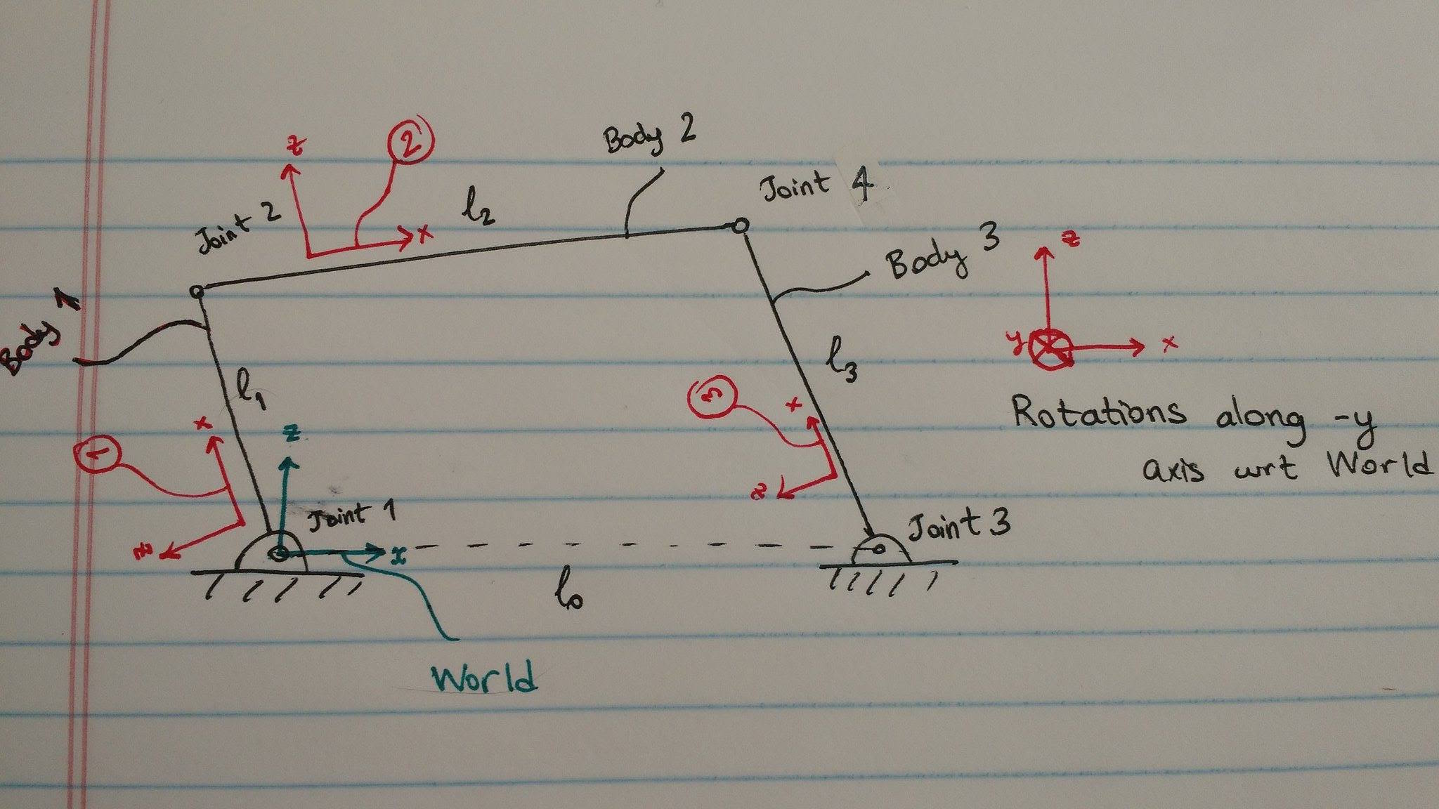
We'll 'cut' the mechanism at joint 4: joints 1, 2, and 3 will be part of the spanning tree of the mechanism, but joint 4 will be a 'loop joint' (see e.g. Featherstone's 'Rigid Body Dynamics Algorithms'), for which the dynamics will be enforced using Lagrange multipliers.
First, we'll define some relevant constants:
# gravitational acceleration
g = -9.81

# link lengths
l_0 = 1.10
l_1 = 0.5
l_2 = 1.20
l_3 = 0.75

# link masses
m_1 = 0.5
m_2 = 1.0
m_3 = 0.75

# link center of mass offsets from the preceding joint axes
c_1 = 0.25
c_2 = 0.60
c_3 = 0.375

# moments of inertia about the center of mass of each link
I_1 = 0.333
I_2 = 0.537
I_3 = 0.4

# Rotation axis: negative y-axis
axis = SVector(0., -1., 0.);
Construct the world rigid body and create a new mechanism:
world = RigidBody{Float64}("world")
fourbar = Mechanism(world; gravity = SVector(0., 0., g))
Spanning tree: Vertex: world (root) No non-tree joints.
Next, we'll construct the spanning tree of the mechanism, consisting of bodies 1, 2, and 3 connected by joints 1, 2, and 3. Note the use of the moment_about_com keyword (as opposed to moment):
Link 1 and joint 1:
joint1 = Joint("joint1", Revolute(axis))
inertia1 = SpatialInertia(frame_after(joint1),
    com=SVector(c_1, 0, 0),
    moment_about_com=I_1*axis*transpose(axis),
    mass=m_1)
link1 = RigidBody(inertia1)
before_joint1_to_world = one(Transform3D,
    frame_before(joint1), default_frame(world))
attach!(fourbar, world, link1, joint1,
    joint_pose = before_joint1_to_world)
Spanning tree: Vertex: world (root) Vertex: after_joint1, Edge: joint1 No non-tree joints.
Link 2 and joint 2:
joint2 = Joint("joint2", Revolute(axis))
inertia2 = SpatialInertia(frame_after(joint2),
    com=SVector(c_2, 0, 0),
    moment_about_com=I_2*axis*transpose(axis),
    mass=m_2)
link2 = RigidBody(inertia2)
before_joint2_to_after_joint1 = Transform3D(
    frame_before(joint2), frame_after(joint1), SVector(l_1, 0., 0.))
attach!(fourbar, link1, link2, joint2,
    joint_pose = before_joint2_to_after_joint1)
Spanning tree:
Vertex: world (root)
Vertex: after_joint1, Edge: joint1
Vertex: after_joint2, Edge: joint2
No non-tree joints.Link 3 and joint 3:
joint3 = Joint("joint3", Revolute(axis))
inertia3 = SpatialInertia(frame_after(joint3),
    com=SVector(l_0, 0., 0.),
    moment_about_com=I_3*axis*transpose(axis),
    mass=m_3)
link3 = RigidBody(inertia3)
before_joint3_to_world = Transform3D(
    frame_before(joint3), default_frame(world), SVector(l_0, 0., 0.))
attach!(fourbar, world, link3, joint3, joint_pose = before_joint3_to_world)
Spanning tree:
Vertex: world (root)
Vertex: after_joint1, Edge: joint1
Vertex: after_joint2, Edge: joint2
Vertex: after_joint3, Edge: joint3
No non-tree joints.Finally, we'll add joint 4 in almost the same way we did the other joints, with the following exceptions:
- both
link2andlink3are already part of theMechanism, so theattach!function will figure out thatjoint4will be a loop joint. - instead of using the default (identity) for the argument that specifies the transform from the successor of joint 4 (i.e., link 3) to the frame directly after
joint 4, we'll specify a transform that incorporates the $l_3$ offset.
# joint between link2 and link3
joint4 = Joint("joint4", Revolute(axis))
before_joint4_to_joint2 = Transform3D(
    frame_before(joint4), frame_after(joint2), SVector(l_2, 0., 0.))
joint3_to_after_joint4 = Transform3D(
    frame_after(joint3), frame_after(joint4), SVector(-l_3, 0., 0.))
attach!(fourbar, link2, link3, joint4,
    joint_pose = before_joint4_to_joint2, successor_pose = joint3_to_after_joint4)
Spanning tree:
Vertex: world (root)
Vertex: after_joint1, Edge: joint1
Vertex: after_joint2, Edge: joint2
Vertex: after_joint3, Edge: joint3
Non-tree joints:
joint4, predecessor: after_joint2, successor: after_joint3Note the additional non-tree joint in the printed Mechanism summary.
Simulation
As usual, we'll now construct a MechanismState and DynamicsResult for the four-bar Mechanism. We'll set some initial conditions for a simulation, which were solved for a priori using a nonlinear program (not shown here).
state = MechanismState(fourbar)
result = DynamicsResult(fourbar);

set_configuration!(state, joint1, 1.6707963267948966) # θ
set_configuration!(state, joint2, -1.4591054166649482) # γ
set_configuration!(state, joint3, 1.5397303602625536) # ϕ

set_velocity!(state, joint1, 0.5)
set_velocity!(state, joint2, -0.47295)
set_velocity!(state, joint3, 0.341)
Next, we'll do a 3-second simulation:
ts, qs, vs = simulate(state, 3., Δt = 1e-2);Visualization
For visualization, we'll use MeshCatMechanisms, an external package based on RigidBodyDynamics.jl.
using MeshCatMechanismsCreate a MechanismVisualizer for the four-bar linkage and open it in a new browser tab (see MeshCat.jl for other options):
mvis = MechanismVisualizer(fourbar, Skeleton(inertias=false));┌ Info: MeshCat server started. You can open the visualizer by visiting the following URL in your browser: └ http://localhost:8701
# open(mvis)And animate:
MeshCatMechanisms.animate(mvis, ts, qs; realtimerate = 1.);This page was generated using Literate.jl.